Augmented Reality is more than Virtual Reality
Retina trackers
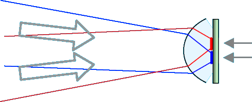
While the display images of AR glasses are projected onto the retina by the optics and the pupil, the retina is vice versa also depicted on the display pane. There it is something automatically in focus, as the optics and also the user's accommodation will always automatically adapt to render a sharp image of the display on the retina, and the same will hence apply in the opposite direction.
Seeing the retina this way would require light sensitive pixels integrated into the display.
With OLED on CMOS displays, this is quite easy, because the CMOS chips already are ideal and widely used for camera chips as well.The retina carries a network of capillary blood vessels, characteristic for each individual. Movements of this pattern and even absolute position in it can be determined as easy as that of a pupil. So this can replace conventional eye tracking. Retina tracking is currently used in eye surgery and has also been explored for military applications, but not in connection with AR.
There are some requirements however. The retina has to be illuminated, and enough light from it has to get to a sensor chip. The display of AR glasses will light the pupil as well, and also project patterns onto it, but it can also be dark depending on content, and the pattern it projects will hardly move with the eye rotation, while the display would have to be following just this rotation, and this even steered from the very tracking data we want to get. So we will need some extra lighting, probably best an infrared emitter right inside the display. This may also be required because of adverse influences from ambient light.
If we have a small display and optical aperture (an advantage in terms of weight and energy efficiency), our retina sensor will also only get a picture if the display and optics keep properly following eye movements. If track is lost, it may be difficult to find the pupil again. If the tracking mechanism is faster than the eye however, this will not happen so often.The restriction of recognition to the pupil could even have its advantages: some people tend to squeeze their eyes heavily, which can be a problem with conventional eye trackers, as there are not enough arc structures left.
Retina patterns can also be used to identify an individual and therefore replace the iris pattern for this purpose.Ambient light from the outside scene will also be on the retina, and it will form an image there. The image sensor in the display will see both, outside and display image, enabling a direct control of proper alignment. Dedicated calibration procedures and continuous refinements of the calibration from differences measured during normal use may even serve as a dynamic adaptation for displacements of the glasses. Even the occluded areas from the mask display can be aligned this way. A changing distance between eye and display assembly would be detectable as well, as it would change the size of the retina pattern.
Could a retina tracker also detect intentional accommodation changes, as are necessary with ghost objects? Without further measures, a deliberate change of accommodation will just blur the retina picture at the sensor side, without any hint about direction. There is perhaps an option to do this: the light field camera.Pixel camera as an angle-to-position converter The principle is simple. Think of a camera that has a tiny micro camera instead of each pixel, with some sub pixels of its own, a device named light field camera [99].
A camera essentially is an angle-to-position converter, so each sub pixel selects incoming light rays from a different angle. By selecting different sub pixels from each micro camera, and combining them into an image, we can change the characteristics of the main lens of the assembly to some extent. Change viewing angle, depth of field, or even focus, for example. So we can immediately tell if focus is going forth or back, by simply comparing contrast for several different sub pixel combinations, simultaneously and instantly.But aren't these tiny sub cameras just too small for a useful angle discrimination ?
Indeed, they are not. A really small display could have 2000 pixels on a length of 1 cm, for example . This is 5 micrometers per pixel, or per micro camera. Light can be bundled enough to form pixels 0.5 micrometers small. Silicon technology can provide structures many times smaller, so this is not a problem to achieve. Hence, each micro camera could have 100 sub pixels or be able to discriminate up to 10 angles in each direction. Not even remotely all sub pixels would be needed, as the possible angles for incoming beams are limited. So angular resolution can be managed, an the same applies for complexity.
The light field approach might well be flexible enough also to provide for some hints if tracking is lost, i.e. the optics aperture missed the pupil, an event calling for immediate remedy, by pupil localization for example.Just recently, real OLED on CMOS displays have been built (by FhG-IPMS) that could implement most of the variants described. CMOS allows to integrate light sensing and signal processing on one chip. Optical mouse chips are CMOS, as are many high end camera chips, or the one-chip eye tracker, for example. CMOS also provides an ideal back circuitry for OLED driving, of course.
Organic LED material can be printed or vacuum deployed (preferred here) directly on the chip. Additional metal layers can then be added on top of the OLED layers. Hence, sophisticated chip assemblies are possible.So this in conjunction with an advanced tracking mechanism may make OLED on CMOS chips, tiny ones with highly enlarging optics, a strong competition to laser displays. One disadvantage may be the usually large bandwidth of LED sources, compared to laser, which could make the use of holographic optics quite difficult and hence disallow some of their most interesting options.
Jan.12,2009
Implications on renderingBi-directional displays could perhaps save a great part of the complicated calculations usually necessary for aligning virtual and real images, and for locating the user's viewing direction.
As the display can see the outside image perceived by the eye (it's own projection as well but that is already the same as if we just take the neighboring display pixels), 100% accurate image alignment (some call it registering) of virtual objects as well as user eye-pointing becomes possible without much calculation or coordinate conversions.
Not only are real and virtual images and mask display occlusions all simultaneously seen by the display's camera just as they are appearing on the user's retina, the capillary structure of the retina is overlaid to this image as well, allowing to locate the center of view to high precision.
There are problems however that we shouldn't neglect.
The greatest difficulty will be the light loss due to apertures: with a large exit pupil of the display optics (that we want to have, because otherwise it would be necessary to move the entire display with any single eye movement), only a small fraction of the display light enters the eye. In the other direction, light coming back from the retina has to pass the eye pupil again, is further attenuated and is also overlaid by a lot of stray light from various directions when reaching the display's image sensors. Hence, separating the image from the retina from the 'noise' of other sources may become quite difficult.
Just doing eye tracking with the retina image is less challenging because there we could use extra lighting (infrared perhaps, together with frequency filtering).Separating the overlaid images for correct analysis may often become difficult as well, but obviously the camera already 'knows' the display image's location at least, as the image coming back from the retina will hit the very display pixels it originated from, hence the directly neighboring camera pixels as well. By subtracting the display image from the camera image, one could already isolate the other information.
This technology, if it works, could be a formidable simplification for augmented reality applications, also regarding the other requirements of fitting the virtual to the real.
For example, positioning a virtual TV at a wall would only require some unique pattern on that wall, which could be recognized by conventional image processing and then would directly deliver the corner coordinates of the virtual screen with perfect accuracy. The mask display's occlusion area may also be adjusted using the display camera image.
Once the virtual screen is activated, it will of course occlude the wall pattern (or the mask display will do this), so we will need enough wall patterns outside the screen area to continue with.Much simpler approaches are possible here as well: hanging a black 'painting' to the wall can deliver a perfect alignment and rendering area for a virtual TV, even for augmented reality glasses not having a mask display. The rendering for such kind of applications gets so simple that it can be implemented with cheap, low-power hardware.
For more sophisticated augmented reality approaches, the three-dimensionality of objects still has to be rendered of course, and we still need orientation cameras as the user will not always look ahead, and also because the display can only see it's own angular range.
But we could do calibrations on-the-fly, by darkening the mask display and the normal projection for a very short time and projecting markers during that time, too short for the user to perceive. It has already been demonstrated, with studio illuminations by projectors instead of the usual beamers, that marks can be flashed invisibly if the mark projection is followed by a negative of it immediately after. For example, add 50% light for 10 ms and subtract 50% for the next 10ms, and nobody will notice anything, while an electronic camera would see it.
home more notes order
Copyright © 2006-2011 Rolf R. Hainich; all materials on this website are copyrighted.
Disclaimer: All proprietary names and product names mentioned are trademarks or registered trademarks of their respective owners. We do not imply that any of the technologies or ideas described or mentioned herein are free of patent or other rights of ourselves or others. We do also not take any responsibility or guarantee for the correctness or legal status of any information in this book or this website or any documents or links mentioned herein and do not encourage or recommend any use of it. You may use the information presented herein at your own risk and responsibility only. To the best of our knowledge and belief no trademark or copyright infringement exists in these materials. In the fiction part of the book, the sketches, and anything printed in special typefaces, names, companies, cities, and countries are used fictitiously for the purpose of illustrating examples, and any resemblance to actual persons, living or dead, organizations, business establishments, events, or locales is entirely coincidental. If you have any questions or objections, please contact us immediately. "We" in all above terms comprises the publisher as well as the author. If you intend to use any of the ideas mentioned in the book or this website, please do your own research and patent research and contact the author.